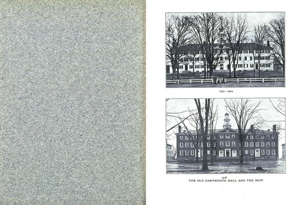
THE HEATING AND LIGHTING PLANT
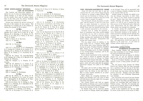
THE Dartmouth heating plant was built in 1898. It was the result of several years of study as to the most practicable and economical way in which to solve the ever recurring heating problem of a growing institution. It is essentially a central station furnishing steam to isolated buildings through underground mains.
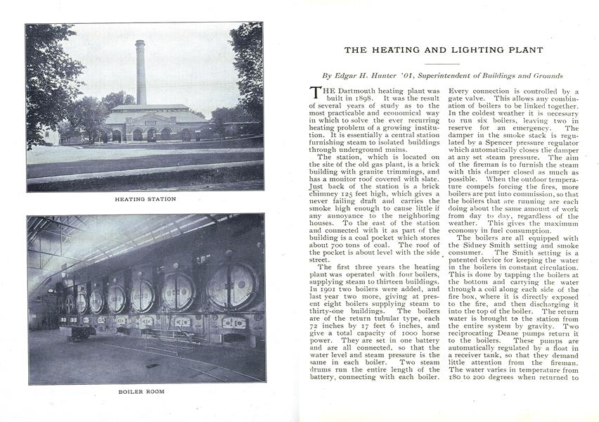
The station, which is located on the site of the old gas plant, is a brick building with granite trimmings, and has a monitor roof covered with slate. Just back of the station is a brick chimney 125 feet high, which gives a never failing draft and carries the smoke high enough to cause little if any annoyance to the neighboring houses. To the east of the station and connected with it as part of the building is a coal pocket which stores about 700 tons of coal. The roof of the pocket is about level with the side street.
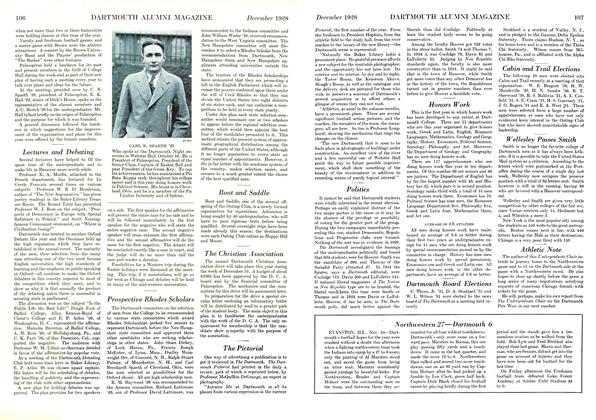
The first three years the heating-plant was operated with four boilers, supplying steam to thirteen buildings. In 1901 two boilers were added, and last year two more, giving at present eight boilers supplying steam to thirty-one buildings. The boilers are of the return tubular type, each 72 inches by 17 feet 6 inches, and give a total capacity of 1000 horse power. They are set in one battery and are all connected, so that the water level and steam pressure is the same in each boiler. Two steam drums run the entire length of the battery, connecting with each boiler. Every connection is controlled by a gate valve. This allows any combination of boilers to be linked together.
In the coldest weather it is necessary to run six boilers, leaving two in reserve for an emergency The damper in the smoke stack is regulated by a Spencer pressure regulator which automatically closes the damper at any set steam pressure. The aim of the fireman is to furnish the steam with this damper closed as much as possible. When the outdoor temperature compels forcing the fires, more boilers are put into commission, so that the boilers that are running are each doing about the same amount of work from day to day, regardless of the weather. This gives the maximum economy in fuel consumption.
The boilers are all equipped with the Sidney Smith setting and smoke consumer. The Smith setting is a patented device for keeping the water in the boilers in constant circulation. This is done by tapping the boilers at the bottom and carrying the water through a coil along each side of the fire box, where it is directly exposed to the fire, and then discharging it into the top of the boiler. The return water is brought to the station from the entire system by gravity. Two reciprocating Deane pumps return it to the boilers. These pumps are automatically regulated by a float in a receiver tank, so that they demand little attention from the fireman. The water varies in temperature from 180 to 200 degrees when returned to the boilers. The cold water feed is taken into the return mains before they enter the receiver, and all the water is fed to the boilers through the Smith setting, which carries it almost directly through the fires before discharging it into the boilers.
The village water system furnishes excellent water for boiler purposes, as it deposits no scale on the boiler tubes. The insides of the boilers are apparently as good at the present day as when they were installed, showing on signs of deterioration.
The underground mains were laid in a manner original with this plant, which was the joint invention of Mr. R. D. Kimball, a Boston engineer, and Mr. A. A. McKenzie, late superintendent of buildings for the College. The method was to split ordinary clay sewer pipe, longitudinally, being careful to keep track of the halves. The lower halves of the tiles were laid in the ground, the entire length of the line. Every 18 feet a split tee pipe was used, the outlet pointing down. In these tees were then set iron roll frames imbedded in cement concrete. These rolls supported the entire weight of the iron steam pipe, which was next laid, and also allowed the pipe to roll freely as it expanded and contracted. The top half or cover of the Akron pipe was then put in place, the same piece going back that originally belonged with each separate under piece. The joints were all made water tight with a rich mixture of Portland cement. The pipe was packed with asbestos sponge filling, as the top was laid. This constructed ail underground steam line at less than half the cost of brick tunnel, the usual construction, and in point of insulation is far superior to pipe covering. 3966 feet of underground main were laid in 1898, which has since been increased to 5959 feet. The entire system is carefully underdrained, the drains being tapped at intervals and diverted to the sewers. This is a vital point on underground heating mains and needs to be as carefully considered as any part of the construction. In some localities it means the difference between success and failure in underground heat transmission. All expansion was taken care of by offsetting the pipe both vertically and horizontally, allowing the pipe to swing on the joints between the ells.
In 1904 the trustees voted to install an electric plant in conjunction with the heating plant, and this was constructed in the winter of 1904-5. Several changes in the heating plant were necessary, to operate the two plants successfully together, but most of these points had been foreseen by those in charge of the original construction, and provisions made for them.
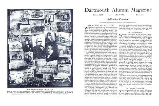
The current is generated by two 75 kilo watt Thompson-Ryan dynamos direct connected to two 125 horse power McEwen engines. Both units were built by the Ridgway Dynamo and Engine Co. A steam pressure of 85 pounds is maintained on the boilers and the engines are connected, by a loop, with both drums, to insure immunity from break-downs. Twenty-two of the buildings are heated with live steam, which passes from the boilers at 85 pounds through a reducing valve in the station to 25 pounds, thence out through the lines to the buildings, where it is reduced to 3 pounds for radiating purposes. The remaining nine buildings are supplied from the exhaust main, which takes the steam after it leaves the lighting engines, and distributes it to the buildings for heating purposes. Making the steam do double duty, first generating electricity and then heating the buildings, is where the great saving in expense is made. A reducing valve in a connecting link between the boilers and the exhaust main, reducing from 85 pounds to 3 pounds, allows steam to flow directly from the boilers into the main when there is not sufficient exhaust steam to heat the nine buildings on this main. This live steam is needed in the four coldest months and in the middle of the day when the engines are not running. This cross connection also serves to maintain a constant back pressure on the engines of 3 pounds. During the summer months, when the exhaust steam from the engines is not required for heating, it is passed through a feed water heater which is placed in circuit with the water supply pipe from the pumps to the boilers, thus saving as much as possible in the coal consumption.
Two connecting links in the mains, which will probably be constructed in the near future, will put the plant in a position where it will be impossible for any ordinary accident to cripple it, even temporarily. A line from Went-worth Hall to Richardson Hall will allow the use of all of the exhaust steam for heat, even through the mild months of the fall and spring. A line from the Tuck Building to the Hub-bard House, together with the line just mentioned, will make two links, thus allowing any building to be supplied with steam from the station, by either one of two entirely separate lines.
The dynamos are self exciting and generate a direct current at 220 volts potential. The fields are both series and shunt wound. The dynamos compound so as to maintain a constant voltage from no load to their maximum capacity, with but little attention from the attendant.
One machine is at present large enough to supply the entire College with light, which leaves the other one free to take up the work in case of any accident to the machine in use. Bach dynamo is run on alternate nights so that both are constantly in readiness for immediate service.
The engines have 14x14 inch cylinders and run at a speed of 250 revolutions per minute. They are automatically regulated to a maximum variation of one revolution, for the varying loads and steam pressures. All the oil for both engines and dynamos is supplied from a reservoir, to which it is pumped by a small steam pump. Waste oil from the machines is piped to an oil filter and from there pumped to the reservoir.
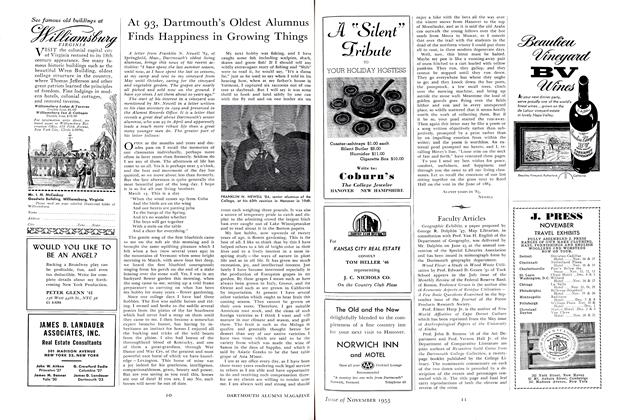
The lighting cables are all underground and are laid in the ordinary electric duct, surrounded by concrete. The cables are lead sheathed and for the most part paper insulated. The College is supplied through ten feeders, averaging about three buildings to a feeder. All of the lines are controlled by circuit breakers on the switch board, which cut out any group of buildings that is giving trouble and prevent it from affecting any other group. Each machine is connected with the switch board by a breaker which protects it from overload on the lines or underload or reversal from the other machine. The switch board is of black enameled slate, framed with white enameled brick. Besides being equipped with the circuit breakers already mentioned, it hasthe usual ammeters and voltmeters, and a double throw switch by which it can be connected with the White River Junction plant. This switch was put in for use in the summer months, in case it was found desirable or necessary to shut down the plant. The back of the board is equipped with copper bus bars, in place of the usual tangle of copper wires, making it easy to trace any trouble in connections or grounding. On the back of the board is a wattmeter for each dynamo, recording the total output of the plant, besides checking the even running of each machine.
The floor of the engine room is of wood, covered with inlaid linoleum. Space is left under the floor for air circulation, which also makes the engine piping easy of access.
Soft coal is used exclusively for fuel. This is hauled from the station in carts, and is discharged into the coal pocket, through the roof. It takes approximately 3,200 tons of coal per year to run the plant, which furnishes steam to 87,000 square feet of radiation. About 15,000 feet of this is indirect radiation. The largest amount of coal ever burned in one day was 25 tons. The coal consumption only approaches this figure when the temperature is from 20 to 40 degrees below zero. The highest average consumption for any one month comes in January, when it takes 18 tons of coal per day to furnish the required amount of steam.
The firing is all done by hand and takes the entire time of four firemen, working eight hours apiece and part of the time of two assistants, during the coldest weather. The whole system is in charge of one engineer, who has, besides the men employed in the station, the services of one assistant on the maintenance of lines. The engineer, in addition to his duties in connection with the plant, has direct charge of all the heating and lighting installations in the new buildings.
There are few plants that are as well equipped to do the work laid out for them as the Dartmouth plant. The entire installation was constructed with the one idea in mind of a minimum cost of. maintenance, and the system is fulfilling all expectations.
HEATING STATION
BOILER ROOM
DYNAMO ROOM
SWITCH BOARD
Edgar H. Hunter '01, Superintendent of Buildings and Grounds
More From This Issue
-
 Article
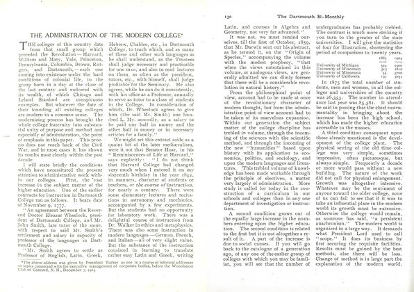
THE ADMINISTRATION OF THE MODERN COLLEGE*
February 1906 -
 Article
THE practical workings of the preceptorial system
February 1906 -
 Article
PRECEPTORIAL INSTRUCTION AT PRINCETON
February 1906 -
 Article
THE RHODES SCHOLARSHIPS
February 1906 -
 Class Notes
SECOND ANNUAL MEETING OF THE SECRETARIES.
February 1906 -
 Article
WASHINGTON'S BIRTHDAY EXERCISES
February 1906